|
|
|
|
|
|
|
|
|
Top
| verified-Beyerdynamic DT-108/109 | |||
| pin # | Use | Color |
For unbalanced wiring, tie yellow and green together and use shield for mic low.
For a DT-108( single ear headset) the red conductor is used for the ear high.
The pin numbers shown are for an RTS BP-325 intercom beltpack. They are for reference only. The pin-designations for another device might be different. |
| 1 | mic shield | Shield | |
| 2 | mic signal (+) phase | yel | |
| 2 | mic signal (-) phase | grn | |
| 4 | ear signal left high | red | |
| 3 | ear signal left low | brn | |
| 5 | ear signal right high | org | |
| 3 | ear signal right low | blu | |
Top
| verified-Intercom Specialties LWS 5-pin | |||
| pin # | Use | Color |
 |
| mic signal shield | Shield | ||
| mic signal high | wht | ||
| ear signal low | blk | ||
| ear signal high | red | ||
Top
| verified-David Clark-Latest TNN Version | |||
| pin # | Use | Color | Pin Numbers reference a BP-325 Stereo Headset Connector. The headset is left/right reversable, therefore the "left" and "right" designations are somewhat academic. The earpiece on the side with the feeder cable uses the red wire for ear high. |
| 1 | mic signal shield | Shield | |
| 2 | mic signal high | wht | |
| 3 | ear low | yel/blk | |
| 4 | ear left high | red | |
| 5 | ear right high | blu | |
Top
| verified-Sennheiser HMD-24x | |||
| pin # | Use | Color | notes |
| mic signal shield | Shield | ||
| mic signal high | red | ||
| mic signal low | blu | ||
| ear left low | yel | ||
| ear left high | gry | ||
| ear right low | grn | ||
| ear right high | wht | ||
Top
| RTS BP-325 Line Connector | |||
| pin # | Use | Color |
 |
| 1 | Common/GND | Shield | |
| 2 | Channel #1 audio and 30vdc | ||
| 3 | Channel #2 audio | ||
Top
| verified-RTS BP-325 Loop/AUX Connector-PGM input mode | |||
| pin # | Use | Color | Uses the Rear Panel PGM Level control |
| 1 | Common/GND | Shield | |
| 2 | Non-inverting input | ||
| 3 | Inverting input | ||
Top
| verified-RTS BP-325 Loop/AUX Connector-Local Power mode | |||
| pin # | Use | Color | notes |
| 1 | Common/GND | Shield | |
| 2 | 12-24VDC | ||
| 3 | NC | ||
Top
| verified-RTS BP-325 STEREO Headset Connector | |||
| pin # | Use | Color | notes |
| 1 | mic signal low | Shield | |
| 2 | mic signal high | ||
| 3 | ear signal low | ||
| 4 | ear signal left | ||
| 5 | ear signal right | ||
Top
| verified-RTS BP-325 MONO Headset Connector | |||
| pin # | Use | Color | notes |
| 1 | mic signal low | Shield | |
| 2 | mic signal high | ||
| 3 | ear signal low | ||
| 4 | ear signal high | ||
Top
| verified-Telex KP98-7 4-pin Headset Connector | |||
| pin # | Use | Color | The HDST microphone input is balanced. To prevent headset cable MIC-EAR crosstalk, tie pin 1 to chassis ground. It is easiest to do this on the rear panel EXT HDSTconnector. |
| 1 | mic signal low | yel | |
| 2 | mic signal high | gry | |
| 3 | ear signal low | gry | |
| 4 | ear signal high | red | |
Top
| Telex KP98-7 5-pin Headset Connector | |||
| pin # | Use | Color | Pin 4 and 5 are tied at the headset connector |
| 1 | mic signal low | yel | |
| 2 | mic signal high | gry | |
| 3 | ear signal low | gry | |
| 4 | ear signal high | red | |
| 5 | ear signal high | tie to pin 4 | |
Top
| verified-Telex KP98-7 9-pin Rear-Panel Headset Connector (DB-9M) | |||
| pin # | Use | Color | Tie pin 2 to pin 6 to unbalance the dyn. mic input. |
| 1 | Dyn. mic + | ||
| 2 | Dyn. mic shield | ||
| 3 | Carbon mic +- | ||
| 4 | Carbon mic Shield | ||
| 5 | Ear signal high | ||
| 6 | Dyn. mic - | ||
| 7 | HDST SW control | ||
| 8 | HDST SW common | ||
| 9 | Ear signal common | ||
Top
| verified-Telex KP98-7 or KP12 Matrix Line Connector DB-9F | |||
| pin # | Use | Color |
|
| 1 | DATA + | ||
| 2 | DATA - | ||
| 3 | GND, Shield Input | ||
| 4 | Station output + (talk) | ||
| 5 | Station output - (talk | ||
| 6 | GND, Shield Data | ||
| 7 | Station input + (listen) | ||
| 8 | Station input - (listen) | ||
| 9 | NC | ||
Top
| verified-RTS 803/802 Front Panel Headset | |||
| pin # | Use | Color |
 |
| 1 | mic signal low | Shield | |
| 2 | mic signal high | ||
| 3 | ear signal low | ||
| 4 | ear signal left | ||
| 5 | ear signal right | ||
Top
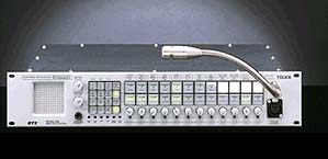
| RTS 803 DB-25 (J111) Connector | |||
| pin # | Use | Color |
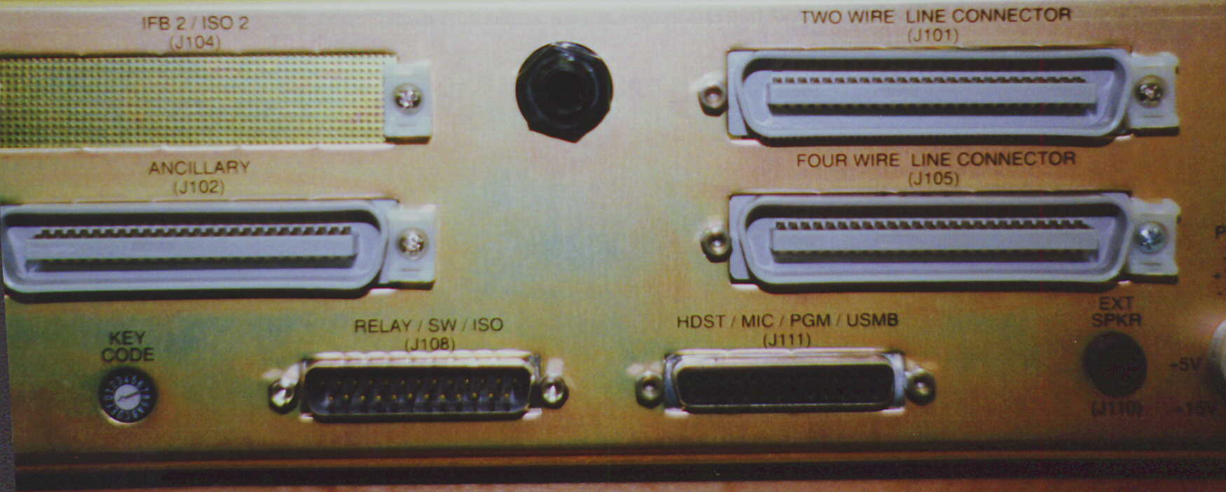 J111 is the female DB-25 connector on the right side of the lower part of the chassis. The USMB output is used to feed an RTS 4000 series IFB panel or it can be routed a patchfield. |
| 1 | EXT HDST mic ground | ||
| 2 | EXT HDST Headphone gnd | ||
| 3 | EXT HDST Right Headphone high | ||
| 4 | Chassis ground | ||
| 5 | EXT Panel mic high | ||
| 6 | EXT carbon headset-common | ||
| 7 | EXT carbon headset-Headphone high | ||
| 8 | Digital ground | ||
| 9 | Program 1 high | ||
| 10 | Program 2 high | ||
| 11 | Chassis ground | ||
| 12 | Unswitched mic out high | ||
| 13 | Chassis ground | ||
| 14 | EXT HDST mic high | ||
| 15 | EXT HDST Left headphone high | ||
| 16 | Chassis ground | ||
| 17 | EXT Panel mic low | ||
| 18 | EXT Panel mic excitation | ||
| 19 | EXT carbon headset-mic high | ||
| 20 | NC | ||
| 21 | Program 1 low | ||
| 22 | Program 2 low | ||
| 23 | Chassis ground | ||
| 24 | Unswitched mic out low | ||
| 25 | Chassis ground | ||
Top
| RTS 803 DB-25 (J108) Connector | |||
| pin # | Use | Color | Male DB-25 connector. Notes |
| 1 | x | ||
| 2 | x | ||
| 3 | x | ||
| 4 | x | ||
| 5 | x | ||
| 6 | x | ||
| 7 | x | ||
| 8 | x | ||
| 9 | x | ||
| 10 | x | ||
| 11 | x | ||
| 12 | x | ||
| 13 | x | ||
| 14 | x | ||
| 15 | x | ||
| 16 | x | ||
| 17 | x | ||
| 18 | x | ||
| 19 | x | ||
| 20 | x | ||
| 21 | x | ||
| 22 | x | ||
| 23 | x | ||
| 24 | x | ||
| 25 | x | ||
Top
| RTS SAP-1626 Camera Connector | |||
| pin # | Use | Color | notes |
| 1 | common | ||
| 2 | common | ||
| 3 | common | ||
| 4 | common | ||
| 5 | common | ||
| 6 | common | ||
| 7 | common | ||
| 8 | common | ||
| 9 | common | ||
| 10 | common | ||
| 11 | common | ||
| 12 | common | ||
| 13 | NC | ||
| 14 | Camera 1 CH-1 | ||
| 15 | Camera 2 CH-1 | ||
| 16 | Camera 3 CH-1 | ||
| 17 | Camera 4 CH-1 | ||
| 18 | Camera 5 CH-1 | ||
| 19 | Camera 6 CH-1 | ||
| 20 | Camera 1 CH-2 | ||
| 21 | Camera 2 CH-2 | ||
| 22 | Camera 3 CH-2 | ||
| 23 | Camera 4 CH-2 | ||
| 24 | Camera 5 CH-2 | ||
| 25 | Camera 6 CH-2 | ||
Top
| Clear-Com ICS-2002/3 Front Panel Headset | |||
| pin # | Use | Color |
 |
| 1 | mic signal low | Shield | |
| 2 | mic signal high | ||
| 3 | ear signal low | ||
| 4 | ear signal high | ||
Top
| ICS-2003Matrix Connector | |||
| pin # | Use | Color | notes |
| 1 | x | ||
| 2 | x | ||
| 3 | x | ||
| 4 | x | ||
| 5 | x | ||
| 6 | x | ||
| 7 | x | ||
| 8 | x | ||
| 9 | x | ||
| 10 | x | ||
| 11 | x | ||
| 12 | x | ||
| 13 | x | ||
| 14 | x | ||
| 15 | x | ||
Top
| ICS-2003 Clearcom Miscellaneous Connector | |||
| pin # | Use | Color | notes |
| 1 | x | ||
| 2 | x | ||
| 3 | x | ||
| 4 | x | ||
| 5 | x | ||
| 6 | x | ||
| 7 | x | ||
| 8 | x | ||
| 9 | x | ||
| 10 | x | ||
| 11 | x | ||
| 12 | x | ||
| 13 | x | ||
| 14 | x | ||
| 15 | x | ||
Top
| ICS-2003 Clearcom Audio I/O Connector | |||
| pin # | Use | Color | notes |
| 1 | x | ||
| 2 | x | ||
| 3 | x | ||
| 4 | x | ||
| 5 | x | ||
| 6 | x | ||
| 7 | x | ||
| 8 | x | ||
| 9 | x | ||
| 10 | x | ||
| 11 | x | ||
| 12 | x | ||
| 13 | x | ||
| 14 | x | ||
| 15 | x | ||
Top
| Verified-Clear-Com AB-100 6-pin (Factory) | |||
| pin # | Use | Color | notes |
| 1 | Mic signal low (-) | Shield | |
| 2 | Mic signal high (+) | ||
| 3 | Headphone Common | ||
| 4 | Ear signal low | ||
| 5 | Ear signal left | ||
| 6 | Microphone Shield | ||
Top
| Clear-Com AB-100 7-pin Headset (TNN Modification) | |||
| pin # | Use | Color | notes |
| 1 | Mic Signal shield | Shield | |
| 2 | Mic Signal Low (-) | Red | |
| 3 | Mic Signal High (+) | Blu | |
| 4 | Ear Signal Low (-) | Shield | |
| 5 | Ear Left Signal(+) | Red | |
| 6 | Ear Signal Low (-) | Mult to pin 4 | |
| 7 | Ear Right Signal(+) | Clear | |
Top
| RTS MCE-325 FP Headset Connector | |||
| pin # | Use | Color |
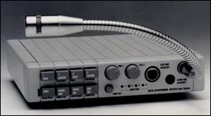 For remote Mic on/off: short pin-1 to pin-6 to turn on the microphone. |
| 1 | HDST Mic LO (-) | ||
| 2 | HDST Mic HI Com. | ||
| 3 | Ear Common (LO) | ||
| 4 | Ear Left HI | ||
| 5 | Ear Right HI | ||
| 6 | Remote Mic On/Off | ||
Top
| RTS MCE-325 DB-25 Accessory Connector | |||
| pin # | Use | Color | This female DB-25 connector has it all. The USMB output is used to feed an RTS 4000 series IFB panel mic signal in. On the 4001 IFB panel, use TB-2 pins 3 and 4 for line level input. |
| 1 | USMB -Hot Mic Out LO (-) | ||
| 2 | EXT Panel Mic Com. | ||
| 3 | Chassis Ground | ||
| 4 | HDST Mic HI | ||
| 5 | HDST Ear HI Left | ||
| 6 | Talk Key #1 Logic Out | ||
| 7 | Talk Key #3 Logic Out | ||
| 8 | 4W-A HI | ||
| 9 | 4W-B HI | ||
| 10 | Common | ||
| 11 | Common | ||
| 12 | ISO Logic | ||
| 13 | Ext +14 VDC in | ||
| 14 | USMB -Hot Mic Out HI (+) | ||
| 15 | EXT Panel Mic HI | ||
| 16 | HDST Mic HI | ||
| 17 | HDST Ear Common (LO) | ||
| 18 | HDST Ear HI Right | ||
| 19 | Talk Key #2 Logic Out | ||
| 20 | Talk Key #4 Logic Out | ||
| 21 | 4W-A LO | ||
| 22 | 4W-B LO | ||
| 23 | Ext +18 VDC in | ||
| 24 | Rem. Mic ON logic in | ||
| 25 | Speaker mute logic in. | ||
Top
| RTS MCE-325 External Speaker | |||
| pin # | Use | Color | DO NOT USE a Metal Shell Connector. This is a balanced speaker driver. Shorting either tip or ring to ground will result in a call to the Telex Service department. |
| Tip | Speaker amp + out | ||
| Ring | Speaker amp - out | ||
| Sleve | No connection. | ||
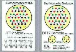
DT-12 connector (a.k.a F/K).
Download Graphic-GIF file.
|
Top

Return to PLsystem.com
Technical Audio Solutions
1003 Joshua Dr.
Mt Juliet, TN 37122
© Copywrite 1997 - Technical Audio Solutions